This project is to convert the DMX 512 signal into the old NSI Microplex (MPX) signal.
The specs for the MPX signal came from this page: Microplex (MPX) Project by Infidigm.
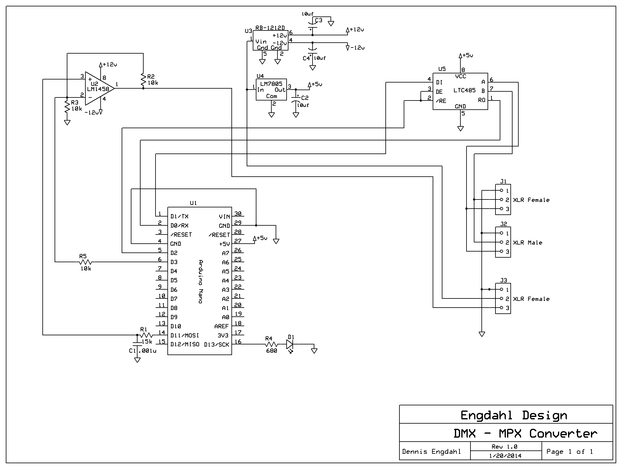
To input the DMX signal, an RS485 interface chip (75176) was used. This is then passed to the Arduino Nano's RX pin. The
Conceptinetics Library was used to place the
DMX channel levels into an array. Then the code in
this sketch
was used to produce the MPX waveform. Only the first 64 channels are converted for efficiency, but that can be changed
in the software if desired. There are two outputs from the sketch. The first is a waveform on D11, which ranges
between 0 and +5v DC PWM. This is smoothed by the low-pass filter consisting of R1 and C1. Then it is fed to
the 1458 op amp,
which multiplies the voltage by 2 (R2 and R3). The resulting wave form ranges from 0 to +10v DC.
The -5v sync pulses are created by using the Arduino D3 pin, feeding through R5 to the negative op amp input.
The op amp power (+-12v DC) is supplied by this device.
The Arduino Nano may be obtained here.
As a diagnostic, the LED on Arduino D13 will light when DMX channel 1 is above 50%.
The original project was mounted in a Radio Shack project box.
The XLR male and
female connectors are mounted
on the ends of the box (male and female on one end, female only on the other.) An external LED is mounted
on the top of the box, and connected to the points shown on the schematic.
The schematic for the project is here.
The printed circuit layout is here. Rename the file to "DMX_Converter.pcb".
(You need the software from expresspcb.com).
Here is an image of the schematic:
Questions and/or comments may be sent to Dennis Engdahl.
 Questions and/or comments may be sent to Dennis Engdahl.